1. This example will require a bit of geometry setup, so I will run through that first.
- Create a Sphere. Set its Radius to 15.
- Apply a Material to the Sphere with a Smoke Map in the Diffuse Channel.
Set the Smoke size to 15 and Swap the Color#1 and Color#2 swatches.
- Animate the Phase over the timeline.
|
2. Now create a Standard Particle Flow.
- For a better visual on the effect, set the Birth Emit times to 0 and change the Amount to 10,000
- Replace the Position Icon Op with a Position Object Op. Assign the Sphere to the Operator.
- For simplicity sake, delete the Speed, Rotation, and Shape Operators.
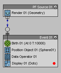
- Add a Data Op under the Position Object Op. and click Edit Data Flow.
- Create an Input Standard SubOp and set it to New In Event.
- Create another Input Standard and set it to Position. Wire the New In Event SubOp to the Position Vector SubOp.
- Create and Output New SubOp and set the Data Type to Vector. Wire the Position Vector SubOp to the Output New
- Right Click on the Output New SubOp and Rename it to Initial Position.
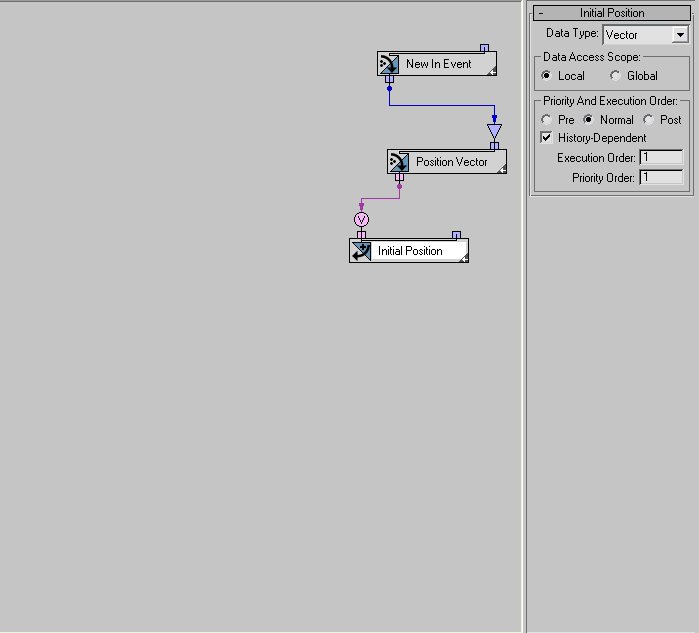
- Now, to reduce some clutter, we will dock all three of these SubOps together. This can be done by dragging one onto another. This serves only to keep things tidy.
|
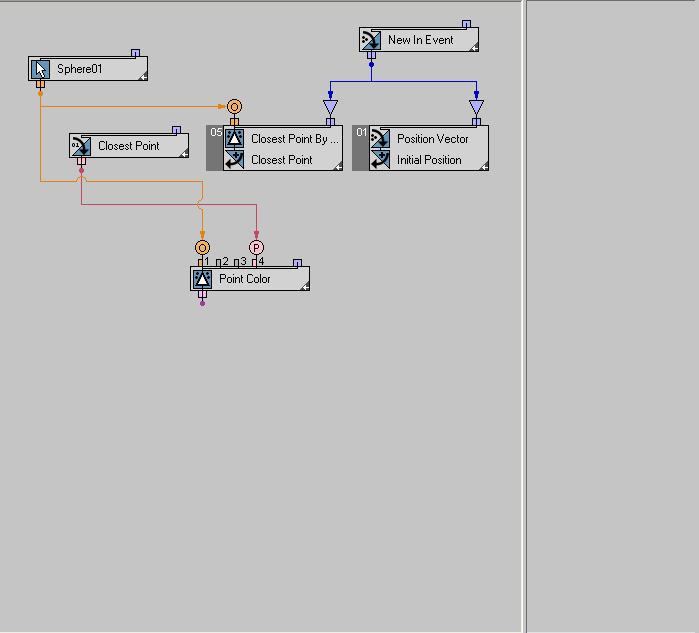
3. We now have the Data we need to begin the displacement.
- Create a Select Object SubOp and pick the Sphere
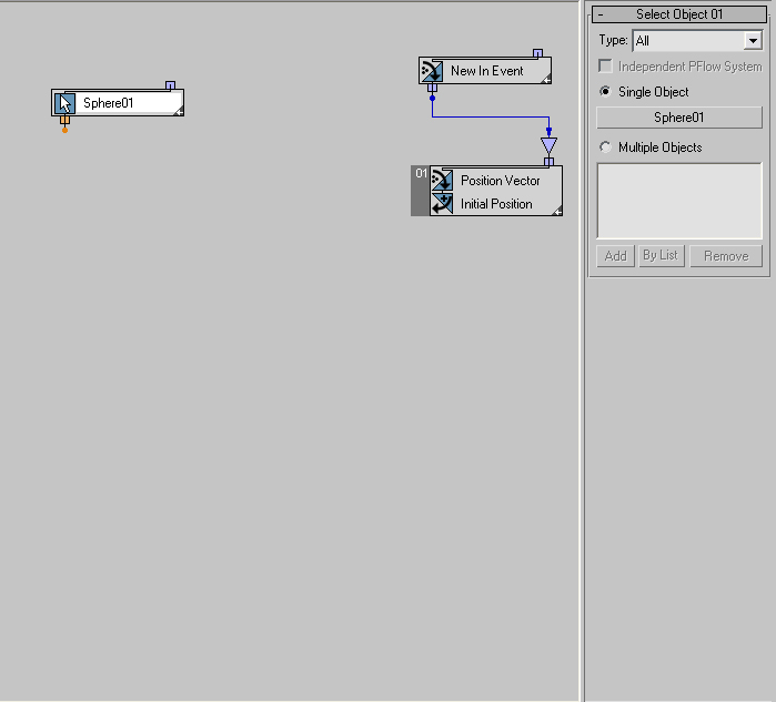
- Now Create a Geometry SubOp and set it to Closest Point By Surface. This will output a point on the objects surface closest to each particle. Wire the Select Object to this SubOp. Since we plan on animating the texture, we need to think of optimizations at this point.
We will assume that the geometry from which we are gathering our Color data from is not deforming and as such we want to only gather our Closest Point data once, upon entering the Event.
So Wire the New In Event SubOp into the Closest Point By Surface SubOp filter. This will dramatically improve the speed of the final Operator as well as maintaining accuracy since the idea is to alter the positions.
- Next, create another Output New SubOp and set the Type to Pair. Wire in the Closest Point By Surface data and rename to Closest Point.
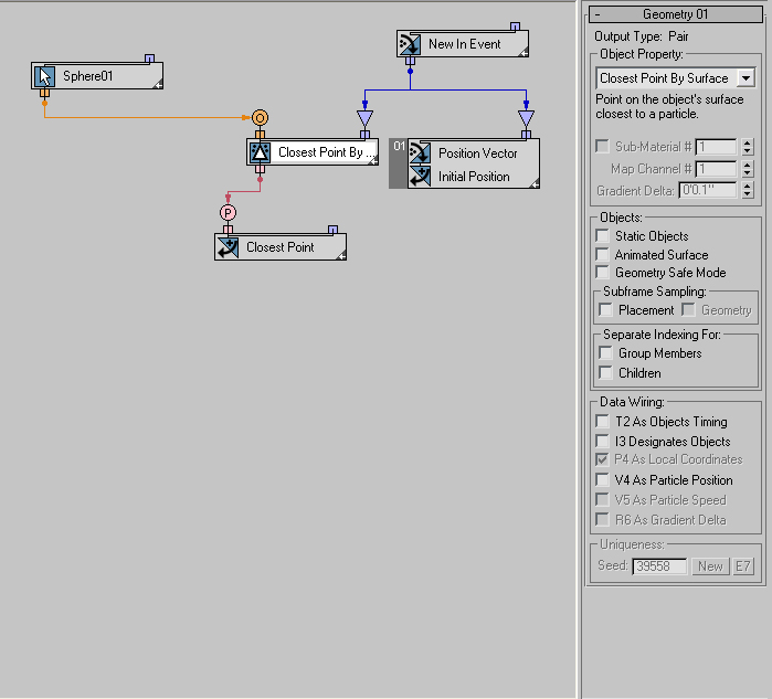
- Create an Input Custom SubOp and set it to get the Closest Point Data.
|
4. Create another Geometry SubOp and set it to Point Color. This will output a Vector of the RGB value of a specified Point on the surface of the Geometry. Keep in mind that the data comes as a float from 0.0 to 1.0 rather than 0 to 255 (0,0,255 = 0.0,0.0,1.0). This makes it a lot easier when using this data as multipliers.
Because we want to use an animated map for the displacement, check the Animate Surface box. This will force an update over time getting us the correct data as the map changes.
We did not do that for the other Geometry SubOps so that we could save calculation time. You will see that it has two inputs. The Object (orange) input, like the Closest Point By Surface, as well as a Point input (pink). Wire the Select Object to the Object Input and the Closest Point Custom Data to the Point input. Now we have the color information we will use as the displacement multiplier.
|
|
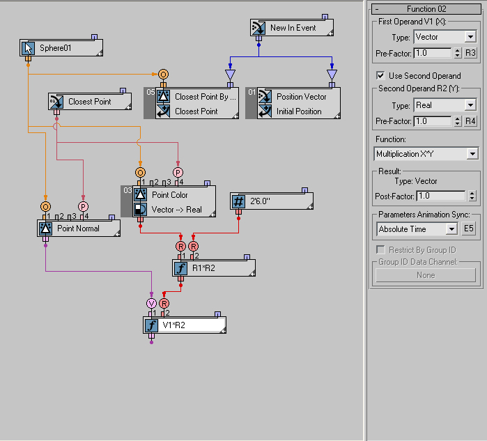
5. We need to create an amount by which we want to displace, so now Create a Scalar SubOp. This SubOp is simply a numeric value. There are a number of Output Types associated with this, but we will just use World Unit here.
|
6. This data needs to be multiplied to our Point Color data. Create a Function SubOp and set the First and Second Operand Types to Real. Change the Function to Multiplication. You will notice that our Point Color data is of the Vector (purple) Data Type and the Function has been set to accept only Real Data Types. We need to Convert the Point Color Vector to a Real.
This will happen automatically once we wire the Point Color Vector to the Function SubOp. Once you do this, a Convert SubOp gets created between the two. Select this and change the settings to Average. This will essentially give us the color Value. Now wire in the Scalar Data and we have the displacement amount per particle.

|
|
7.
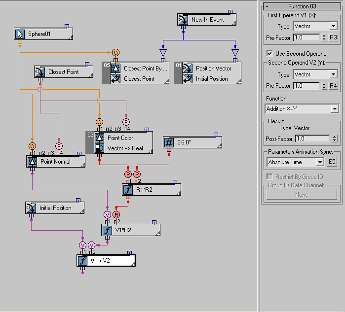
Now we need to get the information for the displacement direction. Create another Geometry SubOp and set it to Point Normal. Again you will see that it has two inputs, Object and Point. Wire in the Select Object SubOp and the Closest Point data. This now gives us a Normal at each particles position.
|
8.
We will Multiply this with the Point Normal Data. This will give us the final offset in the correct direction. To do this we need to Create another Function SubOp. This time we will leave the First Operand Type to Vector and adjust the Second Operand Type to Real. Set the Function to Multiplication and wire in the Point Normal Vector and the adjusted Color Data from the previous Function SubOp.
|
9.
All that is left is to Add the Initial Position Data to the final offset data. Create yet another Function SubOp. Leave the Types to Vector and the Function to Addition. Create an Input Custom SubOp and assign it the Initial Position Data we created earlier. Wire this to Operand 1 and the final offset data to Operand 2.
|
10. Create an Output Standard, set to Position Vector and wire in the Added Vectors.
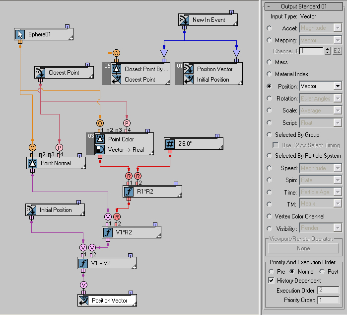
We now have an Operator that will allow for an animated displacement of the particles about the surface of an object.
|
Scene max files:
|